
ARCHITECT AS
Fifth-Year Architecture Thesis
Architect As is aimed at exploring the role of the architect in the future, as well as the way he or she goes about designing and making their work. The thesis will act as a proof of concept for this new and/or modified process.

Architects need to begin to take the initiative to not only fully integrate new technology into their workflow but to begin to take the initiative and to start developing tools, workflows and systems with the goal of creating better architecture that begins to have a wider sphere of influence that starts to innovate the profession.
Tools control how we choose to go about with our work and ultimately it affects how we design. Why should architects limit their creativity? Some believe that constraints can lead to a more rigorous design but what if these constraints are keeping us from something new. We as architects and designers need to spearhead the development of our own means of achieving our desired aesthetics.
It is still up to the architect to use these developments as they see fit and when they see fit. The design and composition of the architecture is still left to the architecture, this way of working is about how we build, and the benefits that are gained. Not necessarily how we built, though with every new development comes a certain style of architecture. But, each style aims expands our design vocabulary.
As architects and designers begin to take the initiative to develop their own tools, systems and workflows, we must not only look at how our developments can just help our own design problems but how they can benefit the profession at as a whole. Your developments may contain key fundamentals and working methods that can help another architect solve their problem.

Before we continue, we need to look at the current digital design process. [A] We as designers continue to iterate and refine our designs until we need to [B] stop and translate the design to another medium, such as the drawing. We do this so the necessary information about the object could be read and understood, so that [C] the design could be fabricated. In the end we end up with [D] our realized design. I should mention that we can go back, but that is not usually the want of the designer since it signifies information being lost in translation.
What I am proposing is a modification to this process. [A] We as designers still iterate and refine our design, however we also design a system or workflow [B] that feeds information directly into the fabrication process. This eliminates the need to translate your design into another medium so that it can be made. In addition to making a more streamlined process, [A-1] the system can now also allows for pieces that are not yet fabricated so to be modified. [A-2] The system can now feed the changes back into the system, then [C] through to the fabrication process without disrupting it. In the end we still end up with a physical object, [D] one that is as flexible in the production process as in the design process.

This creates a feed back loop in the design-to-production phase. Now, one can begin to speculate about the possibilities. On one hand, there is this pragmatic example. Say you've created an assembly. When you are on site assembling, you notice that all of your tolerance was taken up prematurely. With this process and the ability to design while you make, you can account for this tolerance error by modifying pieces before they are made. On the other, if we let external factors such as other persons or participants modify the design, we can create a situation where we as designers can start with a physical object the way we intended and by the time they reach the end of the fabrication and assembly process, have a different, unknown object. This is contrary to the conventional design-to-production process where the goal is to create the known object. Now we have a way to create something unknown.

To return to the idea of 'Architect As', I have begun to outline the the thought process that one undergoes when executing ideas, specifically this one. We must make a myriad of decisions along the way about materials, tools and methods. How the material interacts with the tool. How the tool performs and how to make the tool perform the way you want, or something close to what you want. This forces us as designers to put on many hats and take on many different roles in order to make what we want possible.

In order to get the fabrication process up and running, there was a lot of development that had had to be done so that the robot can begin to machine timber pieces. The first being the development of material handling tools.
Gripper + TOOL HOLDER
PNEUMATIC CLAMP

The first tool is the Gripper. The gripper is used for placing, rotating and orienting the timber members. Before, the gripper had to be manually loaded onto the robot. In order to automate this process, I had to create a tool holder, in a fixed position, for loading and unloading.
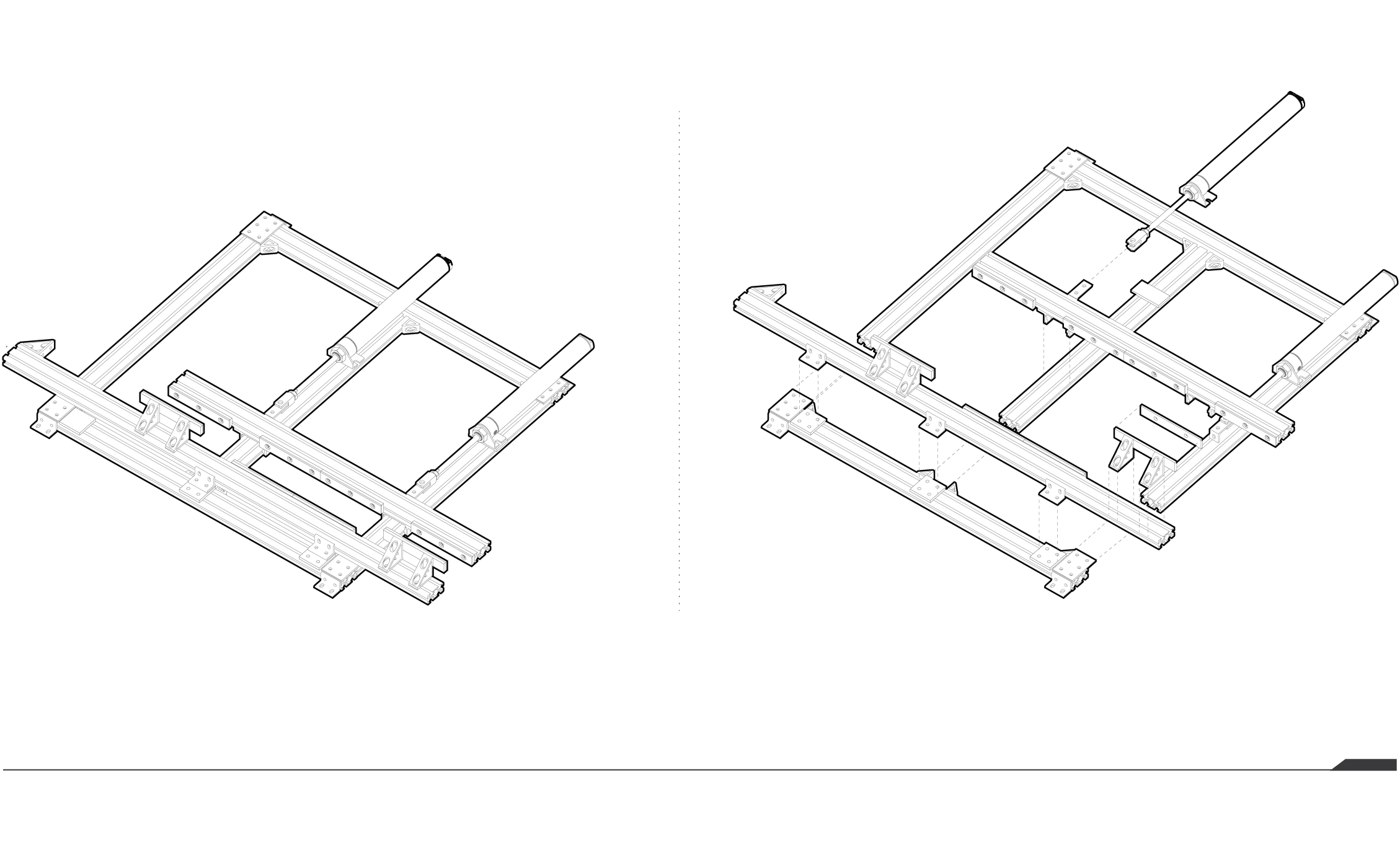
The second tool is the clamp. This is used to secure the piece in place as well as to help one register the timber member when it is first loaded into the clamp.

Scripts
Next, I wrote scripts that would begin to communicate between the digital model and the robot. The first was the notching script. The notching script 'looks' at a stick and locates drive surfaces on the member and automatically generates the tooling necessary to machine out the notch. The Mortise and Tenon script works slightly different. Instead of looking for the drive surfaces the user inputs the parameters of the mortise and automatically generates the tenon that fits. All of this information is then converted into robot code using the HAL plugin for Grasshopper.
TESTS
F001 // Douglas Fir
This was the first test cut using the notching script. The cut was successfully made, and it was surprisingly clean cut. However, it was too deep.
F002 // Pine
This is the first cut using the mortise script. The mortise was cut successfully. It was on center with the stick but the hole was not drilled completely through the stick.
F009 // Hemlock
The next test was repeatability. I replicated the notch above four times to created the reciprocal frame below. The pieces were almost identical, with some being a bit smaller than the others.
F011 // Pine
This is the matching tenon to the mortise above. Similar to the mortise the tenon was cut successfully. However, the hole was very close to the top of the tenon and would cause structural failure if deployed.
Alpha Testing
The thesis will make use of an interface to communicate with designers. Currently I have entered the testing phase for the interface. The interface will be able to graphically represent the assembly in a space outside of Rhino, so that the user does not have to know the ins and outs of Rhino to use the program. The interface will aim to provide the user indirect control (such as creating the over all geometry), and direct control (being able to control specific members) of the final assembly. In the previous semester, I created a test interface with Grasshopper to test user interaction and the integrity of the assembly.
Edwin taught me one of the biggest lessons with his project. The user is always right. Edwin’s goal from the begining was to break the script itself and generate something outrageous. I was initially surprised that the script held up to create the final form, but it did and with that it showed that one thing that I cannot fully control is the creative desire of the user. A user can be as contextual and uncontextual as he or she wishes. The script must begin to place some limitation on the form so that the extremes are contained.
After revising my explanation of how the script works, I gave Heidi the chance of starting the design fresh. What immediately became obvious is that Heidi did not know how to interface with the project with means that moving forward, the interface needs to be simple enough so that users who are not architects can use it or, the target users can only be people who know Rhino.
Nikhil’s test was the one that went off more-or-less fine. He understood the prompt, knew the software, and tried to stay within the limits of the design prevented. The only major issue was time. Which brings up the issue of properly notifying the user of the time constraints to prevent designs from becoming incomplete.
Assembly
After the initial alpha testing in the fall semester, I decided to move from the horizontal tunneling form to a simple vertical stack. The horizontal form required a large quantity of machine time. In addition, since each piece was dependent on the next few pieces to keep itself upright and in position, it cut out the ability to manipulate items close to the stick being machined. By moving to the vertical stacking, I was able to reduce machining to the lateral pieces that bind the two walls of standard pivoting longitudinal pieces together. This embeds all of the intelligence of the system in the lateral pieces leaving the longitudinal pieces reusable from assembly to assembly.

Interface
Now to add an interface to this new assembly. Again working off of some of the lessons learned in alpha testing, I decided to create an interface outside of Rhinoceros in order to reach a wider audience. The interface prompts the user to draw 4 curves and writes the coordinates of the curve to a file. Through Grasshopper in Rhinoceros, I read the files associated with each curve and regenerate them in order to create the two surfaces representing the wall of the assembly that will be used to generate all of the members. The interface allows users to modify members and shift the generates assembly as well. On the Rhinoceros side, I do various error catching that lets the user know when lines are intersecting or if there are short members in the assembly. All of this information feeds into the notching and machining scripts to generate the robot code.
Drawing in the interface.
Catching invalid intersections.
Catching length errors.
Modifying the final assemblies.